The term “geotechnical investigation” refers to the use of various methods to ascertain the physical characteristics of the soil and rock under the earth’s surface at a proposed location. Engineers can use geotechnical investigative methods to determine what kind of tools will be needed to dig through the site efficiently.
It also evaluates the possible environmental effects a project could have on a specific location. This sort of inspection is referred to as a site investigation. The relevance of geotechnical investigations in mitigating damage from earthquakes, base cracks, and other disasters has grown significantly.
Geotechnical investigations can range from being as straightforward as only conducting a visual examination of the site to being as intricate as comprehensive survey and laboratory testing for soil analysis and more.
A] What are the Geotechnical Investigation Parameters?
Many methods are used in geotechnical investigations, including photogrammetry, geologic mapping, and geophysical investigation. A geologist considers the soil properties and establishes the size of the construction that would be secure for the soil being examined.
- The geotechnical investigation could also point out problems like soil liquefaction that could be problematic during an earthquake.
- The geotechnical investigation methods may be used to identify a formation, such as bedrock, capable of supporting a building during an earthquake.
The stability of the foundation is established based on the kind of soil and its capability. Given that foundational failures in buildings can happen, soil analysis is quite important in the building sector.
B] Different Geotechnical Investigative Methods
Geotechnical testing is performed to learn crucial details about the physical characteristics of the soil, rock, and substrate close to a proposed construction site. Geotechnical tests provide critical information for determining whether a site is appropriate for proposed earthworks or constructions.
1. Test Pits
Test Pits allow for the natural visual examination of the subsurface condition. It is beneficial for soil with gravel. In this test, the exposed surface is used for sample and testing. Test pits are a practical way to explore the soil at a shallow depth.
This method involves digging a square-shaped pit and taking soil samples at the necessary depth. Workers can use crowbars to dig out pits physically. Exploration can also be expedited and made more affordable by the use of tractors and motorized excavators.
2. SoilInvestigation
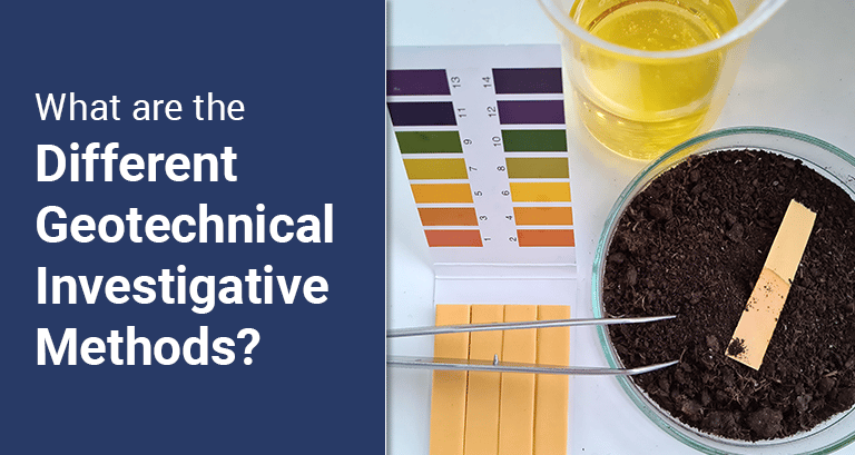
A geotechnical engineer will come to your site to collect and evaluate soil samples for soil investigation testing. The test aids in identifying the soil’s properties, reactivity, and nature. Additionally, it aids in determining the soil’s density, compaction, sand content, and whether any pollutants are present at the location.
The thoroughness and effectiveness of these investigations are crucial to the structure’s serviceability and longevity. The accuracy of the geotechnical report and the data collected from it has a big influence on the project’s design, execution, cost, and safety.
3. PileIntegrityTest
The method of assessing the integrity of individual vertical or inclined heaps by measuring and analyzing the velocity (necessary) and force (optional) response of the pile, caused by an impact device – commonly delivered radially and perpendicularly to the pile head surface – is referred to as a pile integrity test.
Low strain impact integrity testing, sometimes known as a “pile integrity test,” is a popular non-destructive testing method for determining a pile’s integrity and/or length. Pile integrity tests can be used for quality control in new construction or forensic analyses of existing piles.
4. SoilSwellingTests
The soil’s potential and swelling pressure may be determined by calculating its swell index under various field circumstances. Regarding expansive soil, there are two main testing methods. These consist of:
- Plasticity Test: To test for plasticity, a little sample of soil, around one cubic inch, is taken. A hand-rolled thread is made from the soil sample. It is moderately plastic if it rolls smoothly. However, if it doesn’t roll smoothly or break apart, the plasticity is poor.
- Dilatancy Test: Here too a sample of soil is taken and formed into a cube or spherical shape. The soil sample is then given a good shake. The clay has low flexibility if the vibrations force water to seep to the surface.
5. BearingCapacity &SettlementAnalysis
The level of settlement (vertical deformation) that any particular structure can withstand primarily determines the permitted bearing capacity for that structure. A planned structure’s estimated settling must be estimated to establish an authorised bearing capacity.
The structure’s size, shape, and underlying conditions are all crucial considerations in this assessment. Different foundations, soil types, and building types will respond quite differently, and varying buildings will tolerate different levels of settlement.
6. StandardPenetrationTest (SPT)
Standard Penetration Test is a form of in-situ soil test used to ascertain the geotechnical engineering characteristics of subsurface soils, particularly cohesionless soil. The SPT is most frequently used on construction sites to examine soil characteristics and its features.
Soil testing during construction and design is crucial for any building foundation. The test is particularly beneficial in measuring soil’s bearing capacity, angle of shearing resistance, and density. It is also used to identify the cohesive and cohesionless qualities of soil.
7. In-situ CBRTests
When developing pavement for parking lots, runways, or highways, the in-situ California Bearing Ratio (CBR) test is usually used. The sub-strength grade can be assessed with its assistance. Throughout the test, an area-specific cylindrical plunger is continuously introduced into the soil.
It necessitates the employment of a response load, such as a motorized excavator or four-wheel drive vehicle, to supply the force. An alternative method is to use a dynamic cone penetration test.
8. DynamicConePenetrationTest (DCPT)
It is possible to determine the in-situ resistivity of soil to penetration using the dynamic cone penetration test, a method used in geotechnical analysis. The strength of in-situ soil, as well as the depth and thickness of underlying soil layers, may be ascertained with this method.
Before beginning projects involving trenchless installation, this test and others are carried out. The results of the geotechnical investigation provide all the data needed to choose the approach and resources that are most suited for a project.
9. Soil Electrical Resistivity Tests
Calculations and measurements of soil resistivity are essential when constructing earthing systems because an earth electrode’s resistivity depends on the soil’s buried and driven resistance. Resistivity is a measure of a soil’s capacity to oppose electrical current when applied to it.
The movement of ions, dissolved in moisture, controls the majority of the electrolytic flow of electricity in the soil. Understanding soil resistivity helps understand how to attain and maintain the desired earth resistance value during the installation’s lifecycle with the least expense and difficulty.
10. Direct Shear Tests
The Direct Shear Test is an analytical approach undertaken in the field of geotechnical engineering as well as in research that tries to evaluate the shear strength of different types of soil materials.
When being sheared, a material’s highest resistance level is referred to as shear strength. The Direct Shear Test, one of the most widespread and basic tests to determine a soil’s strength, may be carried out on undisturbed or remoulded samples.
C] Different Tools Used in Geotechnical Investigations
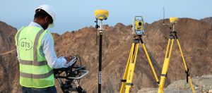
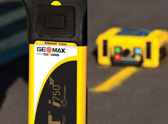
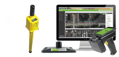
Geotechnical engineers typically use geotechnical equipment to examine the composition and shape of earth components. It can assist in designing earthworks, planning, and building foundations. Some of the tools used in geotechnical investigations include:
Ground Penetrating Radar (GPR)
GPR or Geo radars makes use of microwave energy waves with frequencies ranging from 1 to 1000 MHz. An antenna for receiving signals and a transmitter are needed for GPR. The transmitter radiates electromagnetic radiation into the ground and other substances.
It detects subsurface objects by firing an electromagnetic pulse into the earth and listening for echoes. GPR imaging instruments can also detect variations in ground material composition. When an electromagnetic pulse strikes an item, the object’s density scatters, refracts, and reflects the signal.
The receiver picks up the signals being sent back and logs any deviations. These signals are converted into pictures of the subsurface objects by the software in the GPR system. In this manner, it is utilized to map underground utilities and man-made constructions.
Transmission antenna
Since the antenna transmits and receives electromagnetic signals, the other elements of the GPR system are rendered useless if the antenna malfunctions.
GPR antennas broadcast on various radio frequencies, although they often have a sweet spot where they broadcast most effectively. The “center-frequency” of the antenna is the value that depends on the dimensions of the transmitter and reception components.
The term “antenna bandwidth” is also frequently used to describe the frequency range that an antenna can broadcast at power levels that are 50% or less of its center frequency. The bandwidth of a typical GPR antenna is almost equal to its center frequency.
Conclusion
Geotechnical investigations are required for structural and design engineers to provide design criteria for construction and design strategy for each project. Before any building work begins, a thorough and precise geotechnical assessment is required. By doing this, costly and disastrous events can be avoided in the future.

