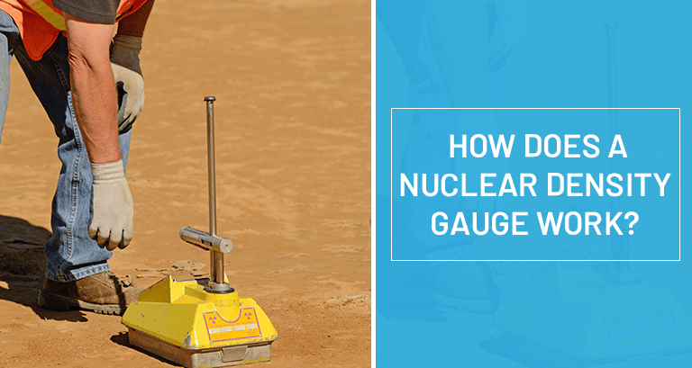
A nuclear density gauge (NDG) is a testing device used to measure the in-situ density and moisture content of test materials, such as soils, bituminous materials, aggregates, etc. It includes a small radiation source for releasing nuclear particles and a sensor for evaluating the nuclear particles. It can also be used to take liquid density measurements.
For nuclear density tests, the gauge is generally calibrated with fluid and gas, which have known densities. The device gives quick and exact results along with density measurements acquired from different cores. The NDG device is suitable for projects that require rapid, multiple testing throughout the day.
1] Types of Gauges
1.1 Transmission Gauges
The source housing and the detector in the transmission gauge are on the inverse sides of the material. The radiation is reduced as it goes through the material, and the indicator estimates a dose rate (or count rate).
If there is a steady calculation, for example, the radiation goes through a consistent thickness of the material or through a pipeline or vessel, the detector will quantify or respond to changes in the thickness of the material through which the radiation has travelled.
If the radiation needs to go through thicker material, its force increases, and the count rate is reduced. The detector comparably senses a decrease in density. This standard is used by the density gauge and the level gauge to control the base & most extreme content in vessels.
1.2 Backscatter Gauges
On the material, the detector & the source housing are mounted on the same side. The detector is safeguarded against primary radiation. The radiation enters the material and collaborates with the atoms and molecules. There will be more communications in thicker or dense materials. The detector estimates the secondary radiations, which are scattered back from the interactions. If there is a steady input, the gauge will demonstrate the material density, and if the thickness is consistent, the indicator will show the material thickness.
The radiation source is carefully chosen to suit the application. Backscatter gauges, which use gamma and X radiation, can be more sensitive to the presence of lighter elements, like carbon, than transmission checks using similar primary radiation.
If neutron radiation is used, the amount of backscatter can demonstrate the number of hydrogen molecules available in the material. This is used for:
- Moisture checks in paper production
- Road gauges – to measure the attributes of tarmac surfaces
- Porosity gauges – to measure the water or hydrocarbon content of subsurface rocks.
1.3 Reactive Gauges
Certain low-energy gamma and X beams can ionize explicit atoms, making them radiate fluorescent X beams of characteristic energy. The detector measurement of the fluorescent X beams shows the presence of specific atoms as well as the sum in the material.
This standard is used by gauges that examine the constituents of materials like minerals and compounds, and by gauges, which measure the thickness of coatings on substrates of disparate materials.
Electrically worked high-energy neutron generators can be used to initiate non-radioactive substances to become radioactive. The radionuclides formed emit characteristic gamma beams, which can be distinguished by their energy. These gauges are widely used to prospect for oil.
2] Process of Nuclear Density Tests
Nuclear Density Gauges determine the number of atomic particles reaching the sensor following reflection from the test material. There are two modes of operation for NDG testing:
- Direct transmission mode: In this mode, the gauge is embedded with a retractable rod by a pre-drilled hole. The rod is brought deep into a mat provided inside the gauge. The radiation discharged from the source strikes the test material and gets dissipated off the sensor because of the loss of energy. If the test material is thick, the interaction between radiation and material is high. Therefore, the quantity of particles identified by the sensor is contrarily connected with the density of the test material.
- Backscatter mode: The retractable rod is inserted into the gauge to such an extent that the bar is at level with the sensor. The radiation transmitted from the source interacts with the test material, loses energy, and gets dispersed toward the sensor. With thick test materials, more radiation is dissipated. This means the quantity of particles detected by the sensor is relative to the material density.
3] Gauge Data Entry
When taking a test, the gauge measures how much radiation is identified throughout a predetermined time frame, like one minute. The detector tubes count the radiation that can go through the material between the lower part of the source bar and the locator tubes.
The denser the material, the lower the amount of radiation that reaches the detector tubes to be counted. These are then converted into a wet density reading. It is referred to as wet density because of the fact that the material under the measure has natural moisture contained in its actual form.
The wet density is compared with a lab standard, commonly the proctor test. But, the gauge’s field wet density reading isn’t as consistent as the lab’s proctor test. Here, compensation for the moisture in the gauge’s field reading is needed, which is where the moisture count comes from.
Guidelines to follow when working with a Gauge on Soil
- Have as much predetermined information as possible and use a scraper plate to prepare the ground.
- Place your drill rod removal device and match the base of the gauge.
4] NDG Moisture Detection
NDG determines moisture by releasing “fast” neutrons that are dialled back or thermalized when connected to the nucleus of hydrogen – a key element of moisture. The Helium 3 tubes in the measure can detect “slow” neutrons. It is an exceptionally immediate relationship, more counts = more moisture. Hence, anything stacked with hydrogen goes about as phenomenal protection from neutron radiation. The plastic packaging around the gauge acts fairly like a radiation safeguard.
5] Reasons for Errors in Gauges
- Environmental factors: Environmental errors are out of the control of the operator.
- Normal hydrogen content: Some soils contain naturally bound hydrogen. The gauge views this natural bound hydrogen as moisture, which might give a false low dry density reading, leading to false low percent compaction.
- Bad luck of the draw: Some DOTs determine the spot, through random determination, the specific place where a test should be performed. If a “soft” spot is chosen, it can provide a poor result for the overall material.
ii. Operator errors: All gauges have small levels of error-clear in their system. You can never achieve an ideal degree of accuracy and precision because of the slight mechanical imperfections and electronic drift. However, the last thing you need is more errors because of operator oversights.
iii. Other errors: Try not to hold back on the gauge calibration. If you need a calibrated gauge, send it to a service center that uses at least a 3-block calibration. Lesser verification devices can increase errors in the gauge.
Gauges are subject to extreme wear and tear. A good service provider checks for and also replaces worn parts. Moreover, circuit boards, detector cylinders and batteries can all affect the accuracy and precision of the gauge. These items should be checked during gauge calibration.
Need more details about Nuclear Density Gauge? Connect with us today!

